Compile and run
In order to run the first example go into the ulambator folder and type `make tutorial4`. An executable will be created. Type `cd ..` and copy it to a work directory of your choice then type `./tutorial4.o` to execute the program.
Tutorial 4 – Droplet anchoring
This tutorial shows how to use a model boundary condition on the liquid interface that incorporates the presence of an indentation in the channel floor as studied experimentally by Dangla et al. It is furthermore shown how to simulate several droplets.
/* Ulambator configuration file Date: 10.02.2014 Version 0.7 */File Header
#include <iostream> #include <stdio.h> #include "../source/matblc1.h" #include "../source/bndblock.h" #include <sys/time.h> #include <time.h> #include <stdio.h> #include <stdlib.h> #include <math.h> int main (int argc, char * const argv[]) { std::cout<<"Welcome to ULAMBATOR++ v0.7\n"; std::cout<<"Unsteady LAminar Microfluidic Boundary element Algorithm To Obtain Results\n";Reading problem parameters
Working directory, viscosity ratio, capillary number, aspect ratio and a folder id.
char* savedir; savedir = new char[120]; sprintf(savedir,"."); double lambda = 0.1; double Ca = 0.001; double RH = 3.0; int folderid = 0;Additionally the radius of the indentation r_hole is provided. Here we set r_hole equal to the channel height.
double r_hole = 1.0/RH;Optional reading of data from command line.
if (argc>5) { folderid = atoi(argv[1]); RH = atof(argv[3]); Ca = atof(argv[2]); lambda = atof(argv[4]); r_hole = atof(argv[5]); } std::cout<<"Configuration folder:"<<folderid<<" R/H:"<<RH<<" Ca:"<<Ca<<"\n"; std::cout<<"lambda:"<<lambda<<" and indentation radius:"<<r_hole<<"\n";Setting up the geometry
Three boundaries, one for the outer flow and two for the droplets.
BndBlock bem = BndBlock(3);Create variables for geometric and boundary value information and initialize the first boundary with 1 panel. The first boundary will be an open domain with constant flow at infinity.
double pos[6]; double bcs[2]; int bnd_id = 0; // first boundary int nb_panels = 1; // number of panels for this boundary int nb_elements=0; // boundary at infinity needs no elements int bnd_type=0; // a fixed wall bem.Elements[bnd_id].Init(nb_panels, nb_elements, bnd_type);Initialize panel 0 of boundary 0 as a boundary at infinity.
int wall_type = 0; // a straight line wall, but unused since there are zero elements int bc_type = 5; // constant flow at infinity bcs[0] = Ca; // velocity at infinity in x-direction bcs[1] = 0.0; // no vertical velocity component bem.PanelInit(bnd_id, nb_elements, wall_type, bc_type, bcs, pos);Initialize boundary 1 as a liquid interface. Twice as much memory is reserved to be on the save side when the deformed drop is remeshed.
bnd_id = 1; nb_elements = 500; bnd_type = 2; bem.Elements[bnd_id].Init(nb_panels,2*nb_elements,bnd_type);Specify the geometric parameters for the circular liquid interface: x, y, radius, perpurbation amplitude and perturbation wave number. Here a droplet with radius one is created at the origin. The interface has no perturbation.
pos[0] = 0.0; pos[1]= 0.0; pos[2]= 1.0; pos[3] = 0.0; pos[4] = 1.0; wall_type = 2; // a circle bc_type = 21; // a liquid-liquid interface bem.PanelInit(bnd_id,nb_elements, wall_type, bc_type, bcs, pos);Initialize boundary 2 also as a liquid interface. Twice as much memory is reserved to be on the save side when the deformed drop is remeshed.
bnd_id = 2; nb_elements = 500; bnd_type = 2; bem.Elements[bnd_id].Init(nb_panels,2*nb_elements,bnd_type); pos[2] = 2.01; bem.PanelInit(bnd_id,nb_elements, wall_type, bc_type, bcs, pos);Save the initial area to enforce area conservation.
bem.Elements[1].initialArea = bem.getArea(1); bem.Elements[2].initialArea = bem.getArea(2);Matrix initialization
The matrix object is created and a pointer to the geometry is passed as well as the aspect ratio, viscosity ratio and capillary number.
MatBlC1 mat(&bem, RH, lambda, Ca); mat.EnableWrite(savedir);The model boundary condition for the indentation, option 3, is set up. One parameter is passed, which is the radius of the identation. All other parameters are as the effective depth of the hole are calculated from a model that we presented in an article.
mat.ChoseStatBC(3, r_hole, 0.0);A Subfolder is created if the index is bigger than zero.
if (folderid>0) { sprintf(savedir,"casestudy%d", folderid); mat.SubFolder(savedir); }Log files are prepared.
mat.LogPrepare(0, "Machine time\n"); mat.LogPrepare(1, "Drop 1: Area and X,Y Position\n"); mat.LogPrepare(2, "Drop 2: Area and X,Y Position\n");Initial lof files and boundaries are written.
mat.LogCfg(); // configuration bem.LogTimeStep(0); // step number and time of the simulation mat.LogRuntime(0); // real time bem.LogAreaPos(1,1); // area and position of drop 1 to file 1 bem.LogAreaPos(2,2); // area and position of drop 2 to file 2 bem.allWrite(); // geometryTime stepping is specified and remeshing activated.
double deltaT = 1.0; int subtimesteps = 50; mat.setTimeStep(deltaT,subtimesteps); bem.RemeshOn(6.28/nb_elements,0);Time marching
The internal loop in SolveRK2 is repeated 100 times, then the boundary and log files are written.
for(int k=0; k<100; k++){ mat.SolveRK2(); bem.allWrite(); bem.LogTimeStep(0); mat.LogRuntime(0); bem.LogAreaPos(1,1); bem.LogAreaPos(2,2); }End of the program.
mat.DisableWrite(); std::cout << "Finished and Exiting\n"; return 0; }Results
In this simulation two droplets are emitted to a flow at low capillary number. Both droplets have a radius of R=1 and are one hundredth of their radius apart. One of the droplets will pass over a indentation in the channel ceiling, which functions as a capillary anchor. One observes in the time lapse image, figure 1, that the lower of the two droplets is stopped while the upper droplet continues its way. Due to the small distance between the droplets there is a hydrodynamic coupling. As the lower droplet is stopped the thin gap between both droplets is filled with liquid, which induces a pressure drop and therefore leads to an attraction between both droplets.
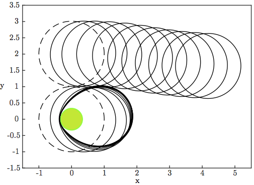
(1) Two droplets streamed from left to right, initial position marked by a dashed line. The lower droplet is a anchored on a indentation, while the upper droplet continues its motion.
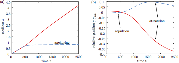
(2) Droplet displacement against time, upper droplet marked by a dashed red line and lower droplet marked by a solid blue line. (a) Center of mass moving in x direction with time, (b) center of mass relative to the initial position in y direction.
We see in figure 2 that the lower droplet becomes anchored and remains fixed. The displacement of the droplets relative to their initial position in the y coordinate (b) shows that the droplets first show a slight repulsion, due to a lubricating flow in the gap.
References:
[1] R. Dangla, S. Lee and C. N. Baroud
Trapping Microfluidic Drops in Wells of Surface Energy
Physical Review Letters 107 (12), 124501, 2011.
[2] M. Nagel, P.-T. Brun and F. Gallaire
A numerical study of droplet trapping in microfluidic devices
Physics of Fluids, 26(3), 032002, 2014.